
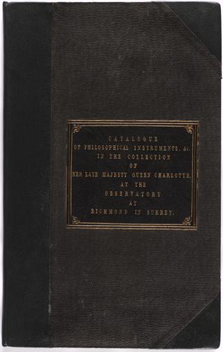
Manuscript entitled: "Catalogue of the Apparatus of Philosophical Instruments, in the Collection of Her Late Majesty Queen Charlotte, at the Observatory at Richmond in Surrey"
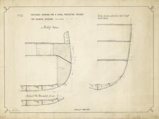
Drawing entitled 'Sectional Drawing for a Steel Protected Cruiser for Colonial Defence to be named'
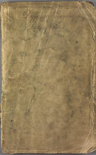
Difference Engine index of parts.
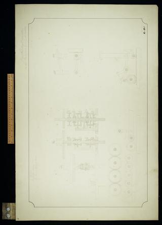
Digit counting apparatus on the two upper wheel selectors.
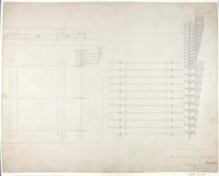
Store variable selectors. Superseding drawing No 2.
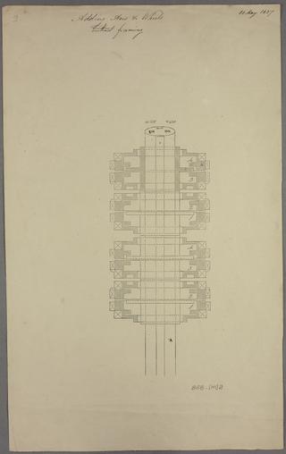
Adding axis and wheels without framing
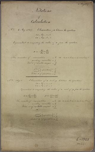
Solution of two simultaneous equations

Notation for the coefficients of the powers of x Computation of the coefficients of a polynomial from those of another divided by a linear term.
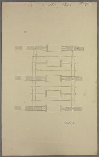
Frame of adding wheels
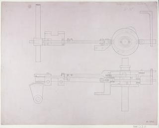
Motion for carrying the tens, plus and minus.

Section of adding wheels and framing.
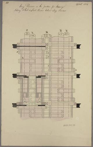
Long pinions in the position for stepping. Adding wheels and short pinions behind long wheels.
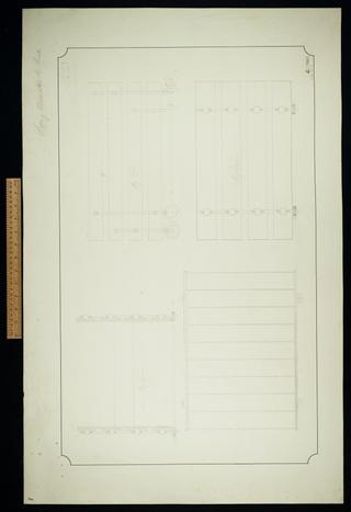
Lifting apparatus by screw. Sheet 9.
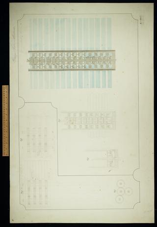
Carriage and racks in sections. Sheet 10.
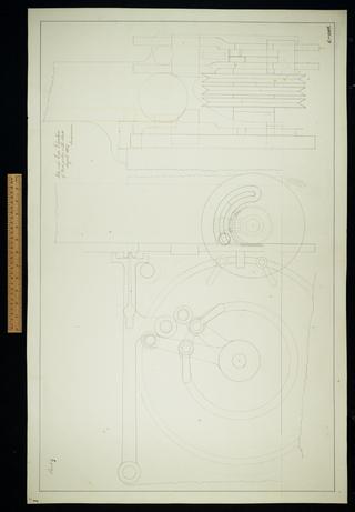
Side and end elevation of feed motion with shade. Second revision.
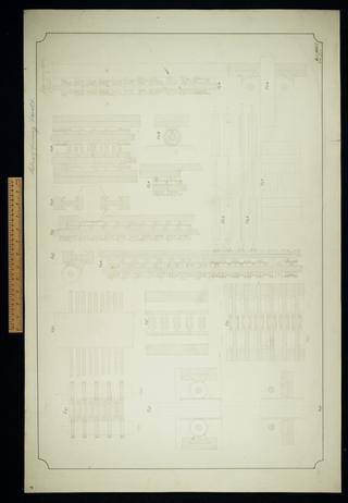
Sections of framing and racks. Sheet 6.

Side and end elevation of feed motions. Showing the bands in different colours.
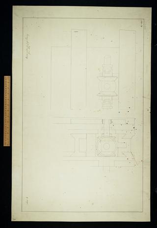
Reverse motion for cross planing.

Back and end elevation of cross slide.

Side and end elevations of feed and driving apparatus
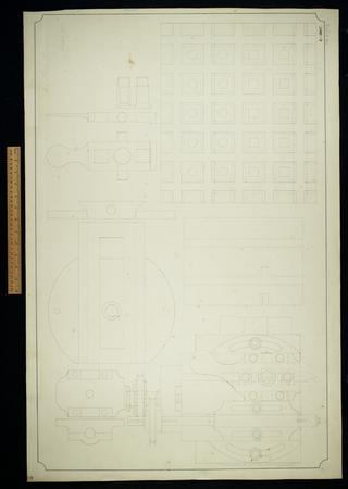
Small planing machine. Sheet 1.
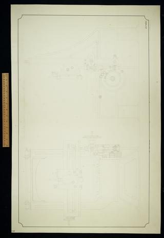
End and side elevation of Large Universal Machine.

Elevation and section of cross slide.

Plan, elevation and section of cross slide.
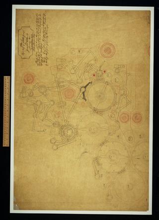
Plan of left half of middle group for General Plan 28.

Plan of Large Universal Machine.
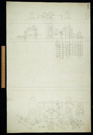
Untitled plan and elevation. Incomplete.
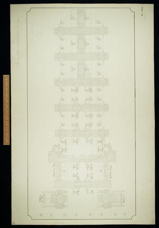
Plan of mill, table wheels and carriage. Sheet 31.
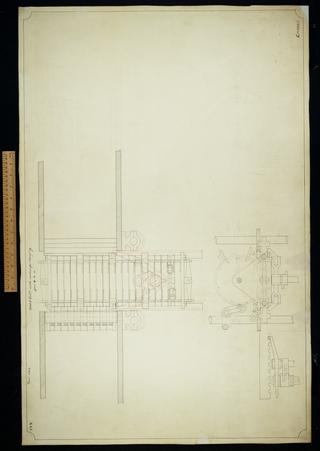
Adding column with motion for changing from plus to minus. Incomplete.
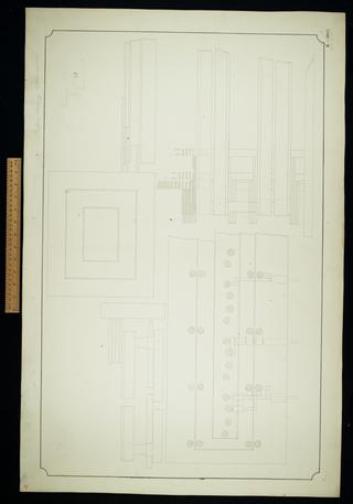
Platform raising apparatus. Sheet 33.

Untitled. A model of six cages was made from this drawing. Incomplete.

Tabulation of a quartic by differences

Generation of the coefficients in the product of two cosine series

Generation of the coefficients in the product of two polynomials

List of variables, their signs and coefficients

Solution of a single linear equation and reduction of two simultaneous equations in two variables to two independent linear equations

Reduction of three simultaneous equations in three variables to two simultaneous equations in two variables

Reduction of three simultaneous equations in three variables to two simultaneous equations in two variables

Tabulation of a quadratic by differences

My Machine 1888 II Plan of driving cams, levers, etc. in initial position.

My Machine 1889 III Development of driving cams.

Sheet 1. Successive reduction of three simultaneous equations in three variables to find the solution for one variable.

Sheet 2. Successive reduction of five simultaneous equations in five variables to find the solution for one variable.
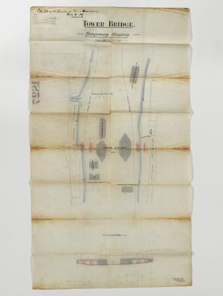
Temporary staging
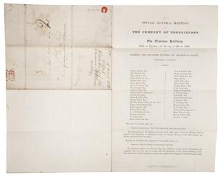
Printed Clarence Railway report
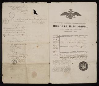
Passport
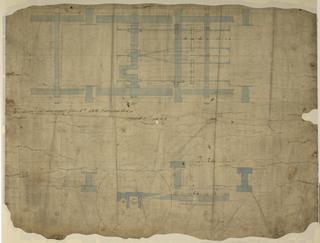
Working Drawing for No 136 Locomotive
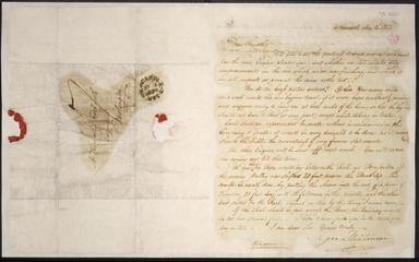
Letter from George Stephenson, Newcastle to Timothy Hackworth, Darlington
